
Simple and cheap way to protect your super caps (video #139 )
In video #133 we used super capacitors to safely shutdown the Rapberry Pi. In the comments, viewers asked about over voltage protection of the super caps. I will show you a big and small and cheap possibility. And I will show you one concept which does not really work.
But why do we have to protect Super Capacitors? And how can we protect them? Most Super capacitors are only specified up to 2.7 volt. If we need higher voltages, we have to connect a few of them in series. To give the Raspberry a save shutdown I used two caps because it runs on 5 volt USB.
Video: https://www.youtube.com/watch?v=NsTAyD2i3rc
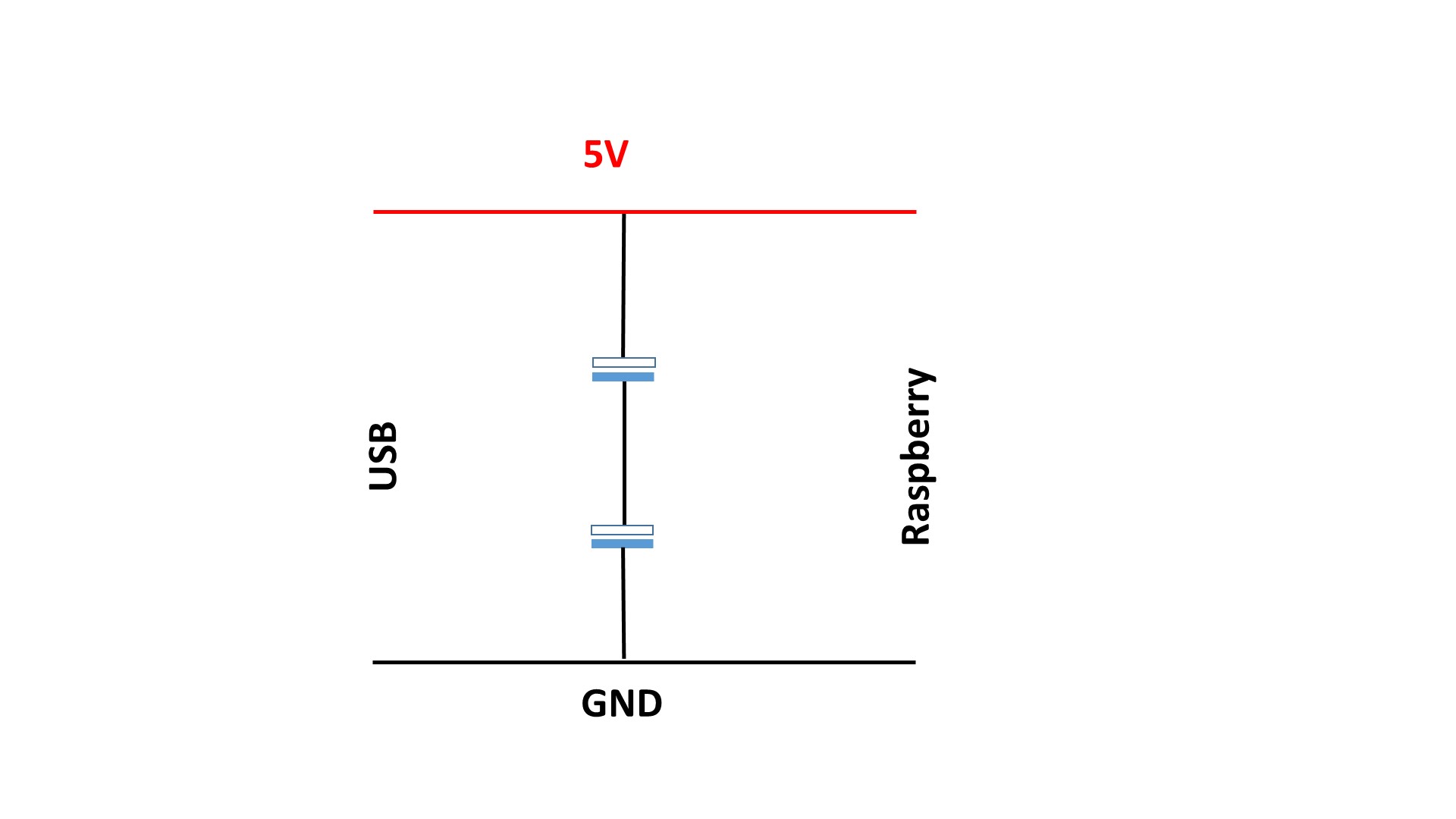
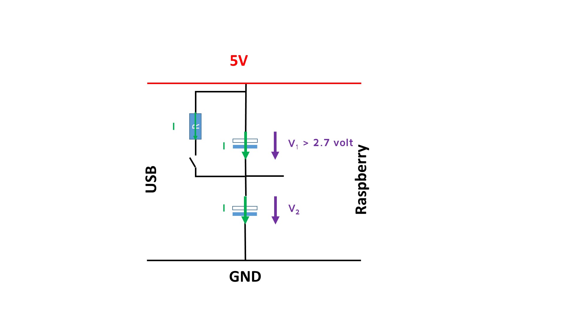
If we charge the capacitors, the same current I flows through each of the caps. If one cap has a smaller capacitance, it charges faster and its voltage can go above the maximum 2.7 volts. To prevent this, we can connect a resistor and a switch in parallel to the capacitors. If the switch is closed, part of the current flows through the resistor and the voltage stays below the 2.7 volts.
We also can replace the resistor and the switch by a 2.4 volts Zener diode
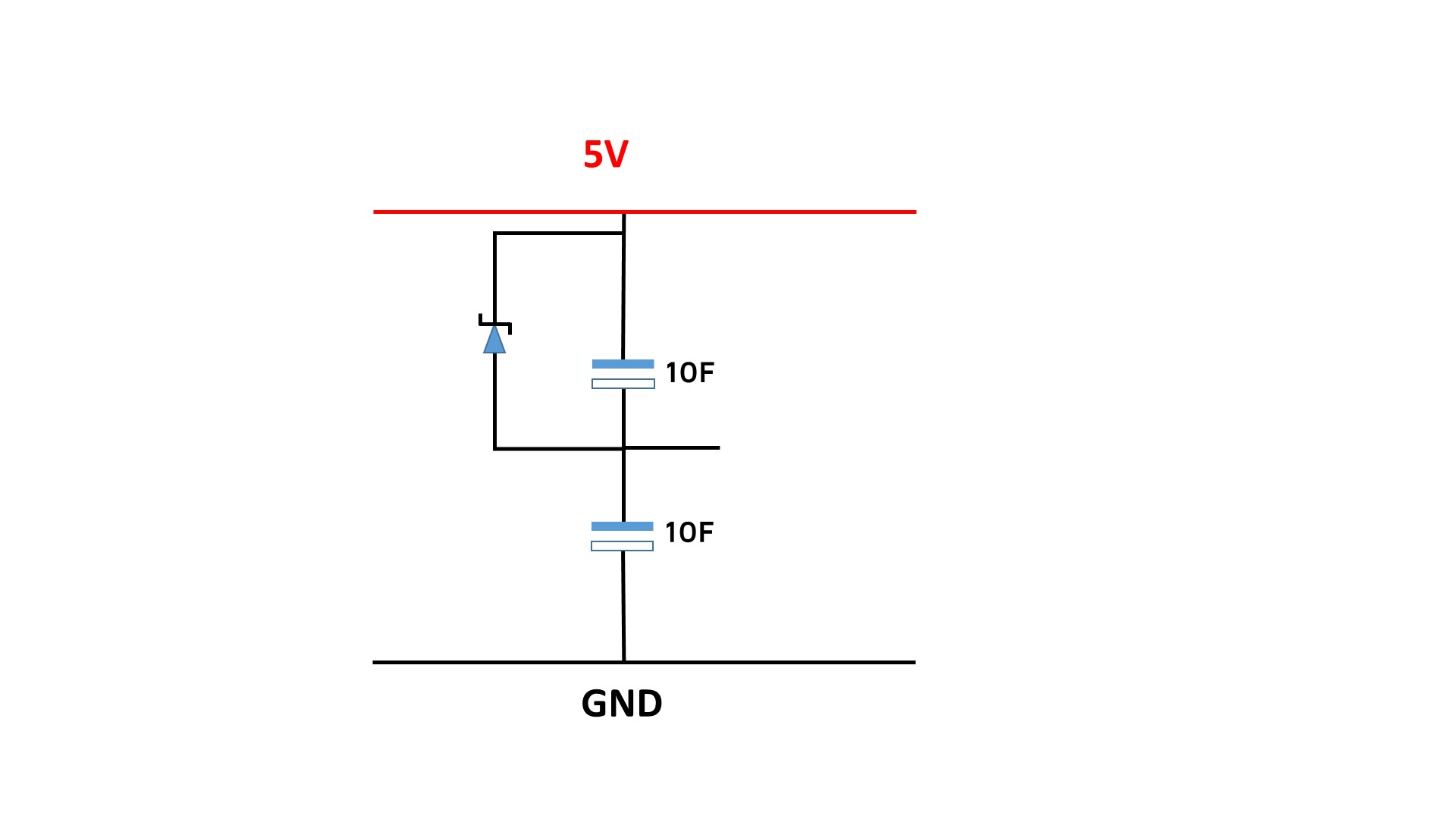
This is a solution for small currents. A better and cheaper solution is to replace the Zener diode with a TL431. This part behaves like a Zener diode with a variable Zener voltage. So, the final diagram looks like that:
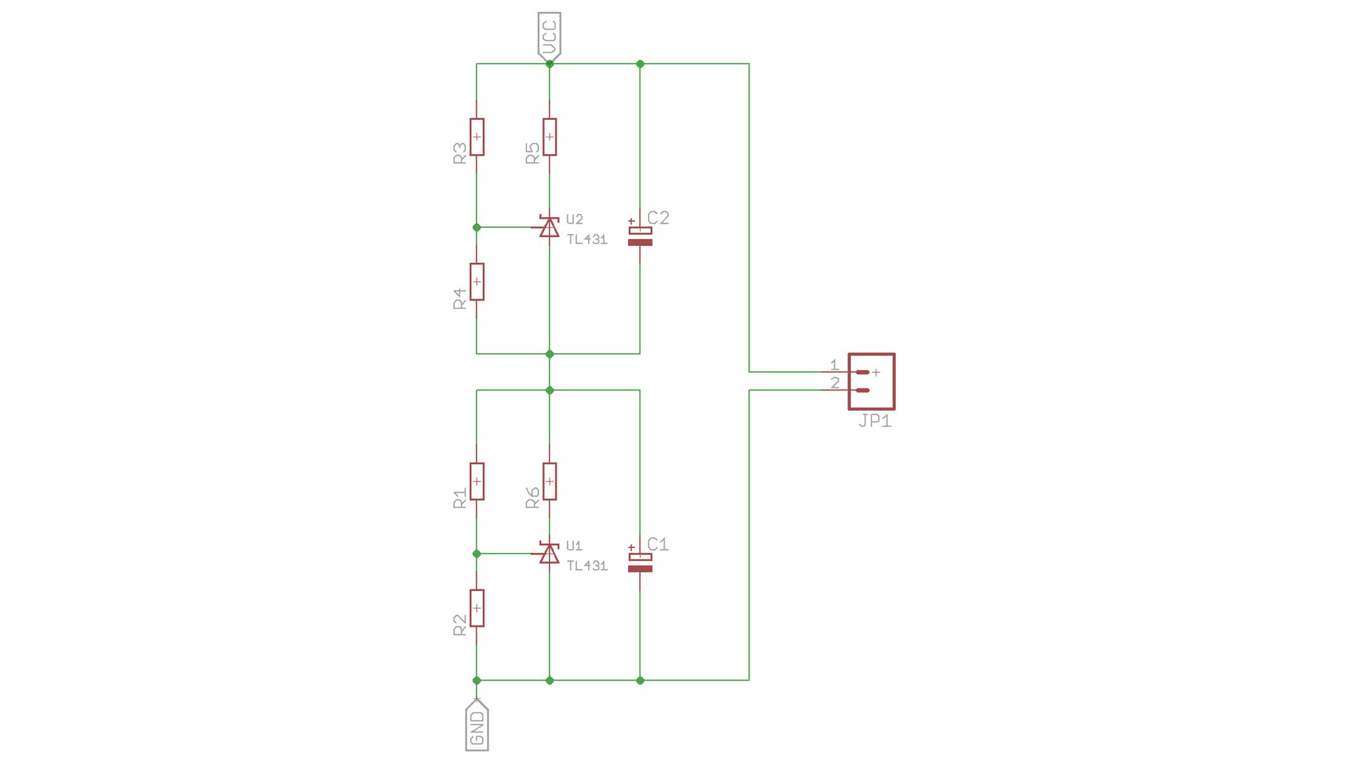
A TL431 can handle up to 150 mA
The formula for the TL431 is: V=(1+R1/R2) x 2.5
And for the resistors: (R4=R2 and R3=R1): R2=0.08 x R1
If you want to use bug capacitors (>>10 F) you can buy ready made protectors:

It also uses a TL431, but it adds a small PNP transistor and a big NPN transistor (8A) to handle bigger currents (the SMD resistors handle max. 1.5A).
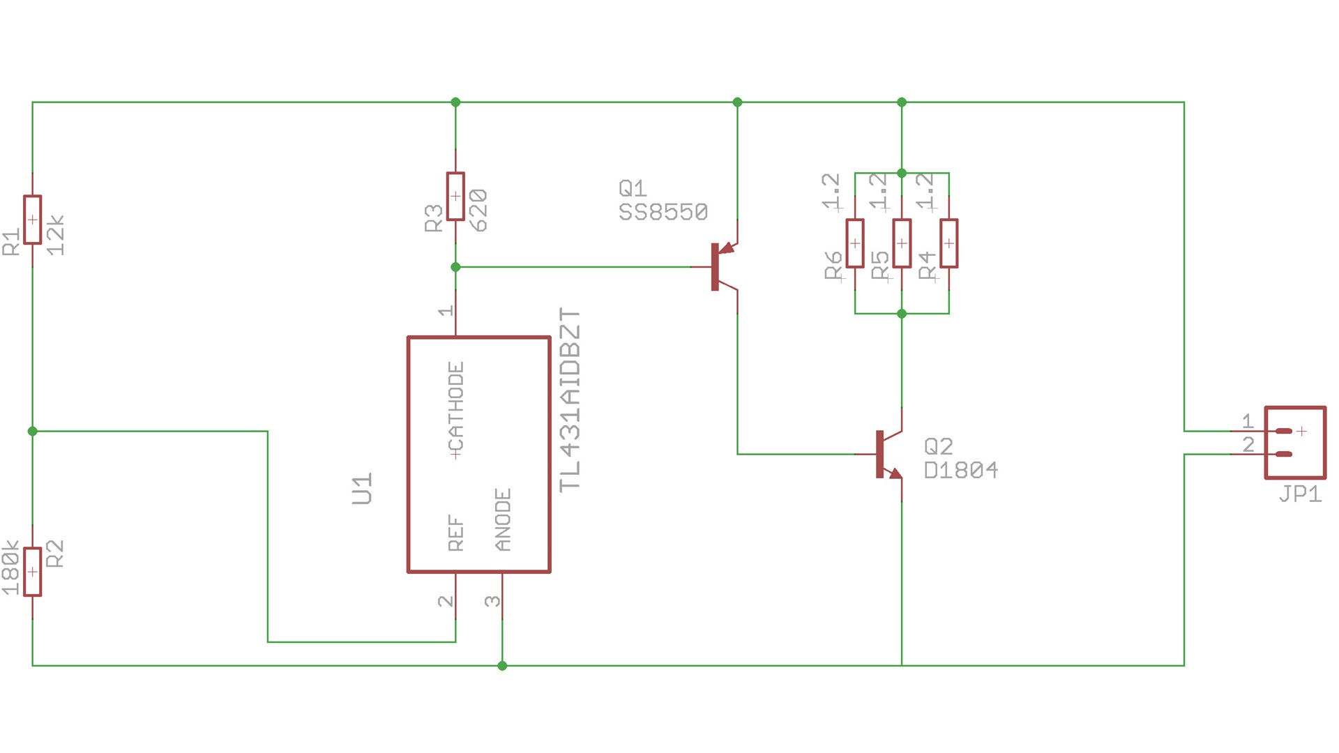
This diagram in the video was not correct (Q1)

31. May 2017 @ 5:34
Great video thanks so much. I have a couple questions. At 10:00 can I assume you doubled the capacity of the bottom capacitor (as per your diagrams)? And that you only had one protection circuit on the top capacitor?
Because the zener is not providing enough current to the bottom large capacitor, too much is still going to the top one. That results in the top (smaller) cap having an over voltage. Is that correct?
23. June 2017 @ 10:16
1. Yes
2. The zener has no clear cutoff voltage. Therefore, it allows voltages above the 2.7 volt (because its resistance is too high).
9. October 2017 @ 23:55
Hello. Thank your for making excellent videos. I think your schematic for the board might still have an error. It seems like it makes sense for R3 to be in series between the cathode on the TL431 and the base of the PNP transistor (Q1). That limits the current through the TL431, which then limits the current through Q1. Otherwise, it is possible for Q1 to see more current than the load resistors (R4-R6)
10. October 2017 @ 0:39
Hmmm. When I wrote the comment above, I was playing with a simulation where I replaced the TL431 with a simple switch I could open and close to see the behavior, but the real circuit doesn’t work if it is modified like I described. It seems like the cathode must be tied to V+ with a resistor.
6. November 2021 @ 17:01
So I’ve been trying to combine this circuit with the circuit from video 133 in an audio project. I purchased two of the balance circuits plus 2x 25F supercaps. They are being driven by a Meanwell 5v4a SMPS. I haven’t built the small transistor shutdown circuit yet and only have the above in circuit.
The problem I’m having is that the Pi 3b is not booting! It seems the charge rate of the caps is to slow and does not pass the threshold fast enough. Any thoughts?
5. December 2021 @ 21:14
When I examine the PCB I noticed that the base of Q1 must be tied to conjuntion point of R1 and R2, not to cathode of U1. I made the circuit as I mentioned and It works…
7. March 2022 @ 8:15
Hello Andreas.
For a friend who is going to make a world trip with his bike , i designed a little 5V power supply from a dynamo HUB which is only 6V 3W (shimano) , the purpose is to charge his gears like smarphone , gps and others stuff.
So a made a double rectifier with mosfet to minimize the loss ans i use a boost buck converter which input works between 4.5V – 9V , (Traco power ) the ouput is 5V and charges well , but its long and it shutsdown as soon he stops cycling. (of course )
I would like to optimise my design by using supercap just after the rectifier to help the buck boost converter and maintain a voltage like 5.3 at its input.
So the mosfet rectifier, 2 supercaps in serie with a TL431 for each and then the buck boost converter.
I just wanted to know your thoughs about that or if you have any ideas or advices.
Thx a lot for your videos
73
F4IGA
7. March 2022 @ 15:42
I do not see a lot of advantages with a Super cap. If there is a battery all current always charges it. If there is no consumer it is best to switch everything down (as you already do). I am also not sure if you need the boost part. I assume the voltage quickly gets to 6 volts if he is driving. The energy content of the time below 6V is probably minor. What could be more important is to adapt the current consumption to the optimum power delivery of the dynamo (like MPPT on solar panels).
But if it does not hurt the efficiency and does not take too much space it does not hurt.
8. March 2022 @ 20:01
The purpose of the supercaps was to keep a little amount of energy when you stop cycling for a short period of time, for exemple at a cross road with a STOP , and to harmonize the cycling pace , i belived that if you have a poor pace maybe the voltage is less than 6V (i have to test that) and the boost part would be justified in this case to keep charging. But indeed it’s maybe not useful just a good ocassion to play with super cap. 🙂 thanks