
Safe Shutdown for Raspberry Pi with Super Capacitors (#133 )
Idea of a Shutdown-Protector
Create a signal for a GPIO of a running Raspi as soon as the supply voltage is interrupted to trigger a software which immediately starts a controlled shutdown. And to build some sort of “energy source” for a few seconds, until this shutdown is finished.
Instead of batteries, we use small super capacitors of 10-15 Farad.
Diagram for the “Protector”
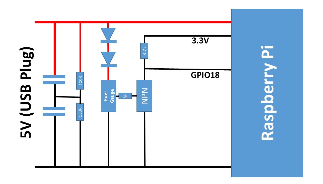
The two super caps have parallel resistors to “bleed” them in case of power loss. If the power is away for a few minutes, the Raspi boots if power is applied again.
Some viewers also suggested some sort of over current protection from the USB plug to the super caps. This can be done with a small resistor. However, thin USB cables have a similar effect.
Link to another proposal: http://www.hackerspace-ffm.de/wiki/index.php?title=Raspi_EDLC_UPS


24. April 2017 @ 13:50
Hi,
What do you mean by “If the power is away for a few minutes, the Raspi boots if power is applied again.” ? Does it make any difference if the power is off for a few minutes or a few hours? Thanks,
24. April 2017 @ 17:23
The Rpi boots automatically, if it is powewd on. It does not boot, if you shut it down and keep it powered. So, the capacitor have to discharge before power comes back. Thats all.
26. April 2017 @ 10:37
Hi Andreas,
love your work. This video was really interesting for me as I have the following set up;
RPi Zero W connected to Sparkfun Sunny Buddy MPPT charge controller
30W solar panel
7800mAh Lithium Ion battery.
my mppt controller charges a battery and RPI zero during the day, at night the RPi discharges the battery until the battery’s low voltage circuitry disconnects the battery from any more drainage. The next day the battery remains in this disconnected state eventhough the charge controller is receiving energy from the solar panel. I have to manually disconnect & reconnect the battery to get things working again, i.e. to “wake up” the battery.
Do you have any ideas how I could have a circuit power down/ disconnect the RPi load when battery voltage gets down to 2.8V and reconnect the load and wake the battery when battery voltage reaches 3.0V or when the solar panels starts to charge again?
I’m a bit lost…
Thanks,
Paul a big fan 🙂
1. August 2018 @ 20:32
Can you post link to parts ?
Thanks
10. October 2018 @ 21:49
Parts list would be good.
I can’t believe no one is selling these..
17. November 2018 @ 5:48
Moin Herr Spiess
ich suche seit einiger Zeit eine Möglichkeit, meinen Raspi vernünftig runter zu fahren, wenn das Gerät insgesamt ausgeschaltet wird. Wenn man wirklich nur das möchte, sind die bekannten HAT’s mit Batterien nicht sinnvoll. Die Lösung mit den Supercaps ist dafür die cleverste Lösung.
Sie haben sich viel Mühe gemacht und die Videos gedreht, die Scripte veröffentlicht, diesen Blog dazu geschrieben und Schaltschemata gezeichnet. Und ich halte ihre Lösung für die beste Variante der mir bekannten vier ( juice4halt, Hackerspace FFM, Hackaday.io)
Ist es möglich eine reproduzierbare Teileliste zu bekommen? Die Batterieanzeige benötige ich auch nicht. In wie weit kann man die weglassen?
Ich beschäfftige mich eher selten mit solchen Dingen. Daher bin ich nicht sicher.
mfg Johannes
17. November 2018 @ 16:25
Die Teile (Dioden und Transistor) sind ja ersichtlich. Sie sind nicht kritisch, da geht fast alles was so im Labor rumliegt. Vielleicht machst du mal einen Prototypen?
Die Anzige verwende ich um die Spannung für das Abschalten zu bestimmen, so dass man sie nicht weglassen kann.
18. November 2018 @ 1:29
😉 in meinem privaten “Labor” liegen entweder schwere Maschinen herum, die man für den Hausbau braucht oder alles was man dafür braucht, ein 4jähriges Mädchen zu bespaßen. Beruflich habe ich es eher mit Beatmungsmaschinen, Pulsoxymetrie und Spritzen…. schlechte Voraussetzungen um mal eben was elektronisches zu basteln und mit dem zu arbeiten, was so rumliegt. Daher meine Frage nach einer Teileliste.
Aber sei es drum. Was nicht rumliegt, kann man ja kaufen. Mal abgesehen von einem vernünftigen Voltmeter und einer Lötstation, die schon lange auf meiner Einkaufsliste stehen, versuche ich mich dann mal mich durch conrad und Aliexpress zu kaufen. Mehr als schief gehen kann es nicht. Ein paar Fragen werde ich aber sicher haben. Kann man dich auch direkt per mail erreichen? über die Kommentarfunktion ist es doch eher mühsam.
29. March 2019 @ 14:29
I’ve always been concerned that adding too much capacitance to the output of a power supply will degrade it’s stability. Is it a problem? Adding a series resistor to the super caps probably won’t work because they need to supply 0.5 A or more during shutdown.
14. April 2019 @ 11:51
This question does not have a simple answer. Generally, power supplies are protected against overcurrent. So adding capacitors is not an issue.
28. December 2019 @ 12:20
Hello Andreas,
Love your work.
RE RPi Shutdown Protector
In video #133 a contributor alerted you to a KA75xxx chip.
Would you be able to show a diagram of how that chip could replace the battery fuel gauge shown in this article.
Just getting started, thanks in advance.
28. December 2019 @ 21:30
Maybe I will once make a video about these chips. It is on the list…
30. December 2019 @ 9:24
Thank you.
22. February 2020 @ 17:58
The link does not work anymore.
Here is a copy: http://web.archive.org/web/20180824134736/http://www.hackerspace-ffm.de/wiki/index.php?title=Raspi_EDLC_UPS
1. May 2020 @ 8:59
Great guide. i have 1 question, short answers is oke.
Can i use this guide (capacitors 100F, 2x50F) with raspberry pi 4 + 4″ touchscreen (0.88A+0.16A)? ( i have try google: capacitors calculator result is i am not that smart).
any help will be great, thx
ps. single KA75450 SOT-89 is very hard to get, going for MAX803L i think.
3. June 2020 @ 19:34
I did not try. So I do not know 🙁
8. May 2020 @ 13:40
I’d like to try this out on a raspberry pi 4, but I’m a bit concerned about the inrush current when charging the supercapacitors. My powersupply can deliver 10A at 5V. what series resister would you suggest that doesn’t drop the voltage too much and how many watts would it need to be?
Would 2 10F supercapacitors be sufficient?
3. June 2020 @ 19:35
The Pi4 needs more power, but you have to find out how big of a capacitor you need.
13. December 2020 @ 11:36
Thank you for making this article!
I wish to know if someone has made a PCB design to put all the hardware on top of a RP3